Robotics Manufacturing Factory
From components to an integrated unit: design, assembly, programming, inspection and qualification before deployment.
View facilities & explanationsInside the space,
the details take shape.
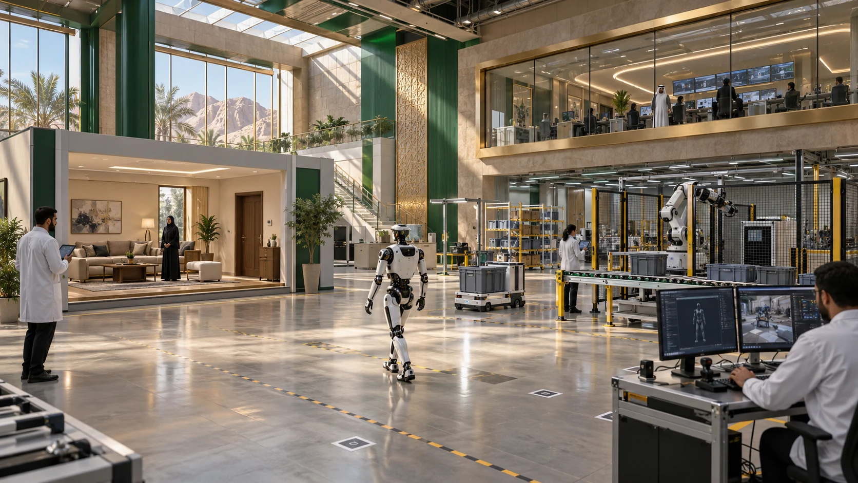
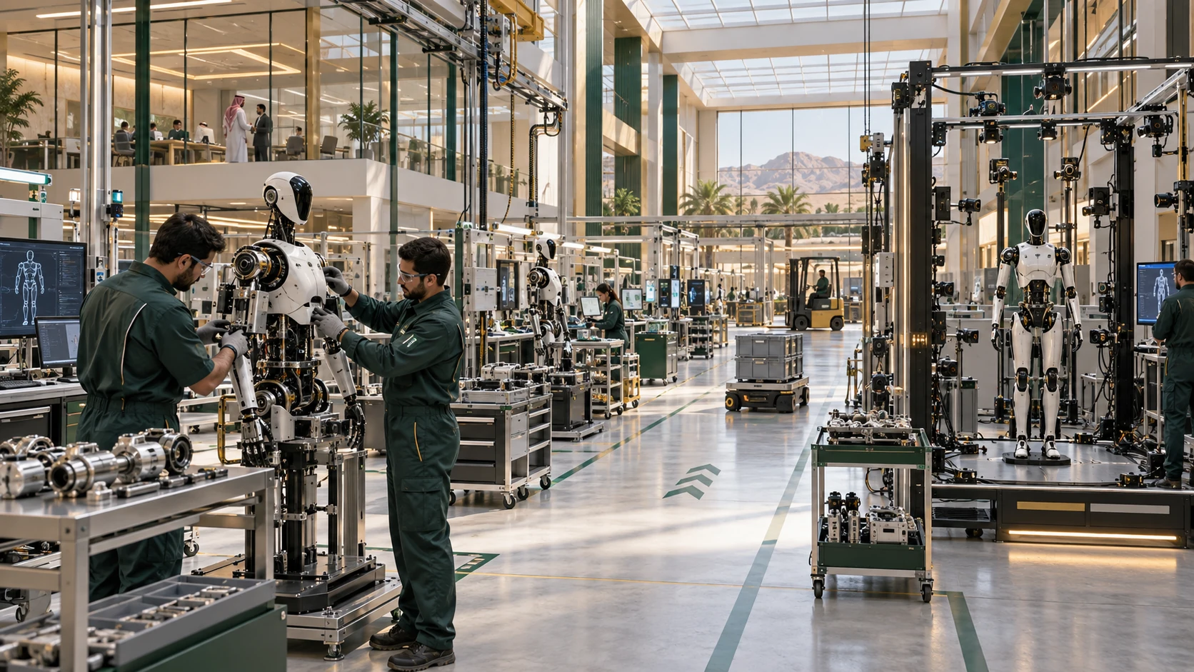
Sequential assembly cells sit along a materials corridor, moving from structure to motion, sensing and computing. Calibration and testing follow, with a separate area for units requiring rework. An independent observation route explains production without entering assembly.
A clear service route and defined work areas
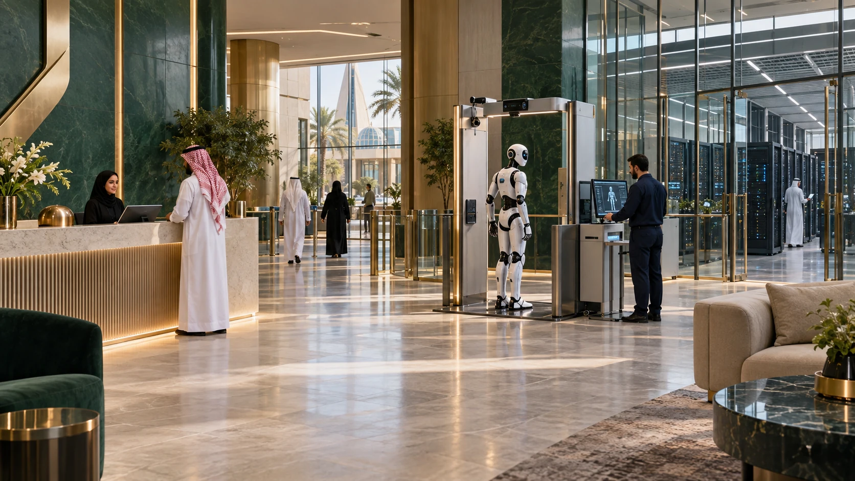
Access separated by the function of each space
Review and documentation points between work stages
Every unit, explained.
Every facility is explained below. Use the index to jump directly to a facility.
Product engineering & parts preparation
Review configurations, drawings and the bill of materials; prepare each unit’s parts kit and authorized alternatives.
Configuration record and traceable parts kit.
Assembly & integration cells
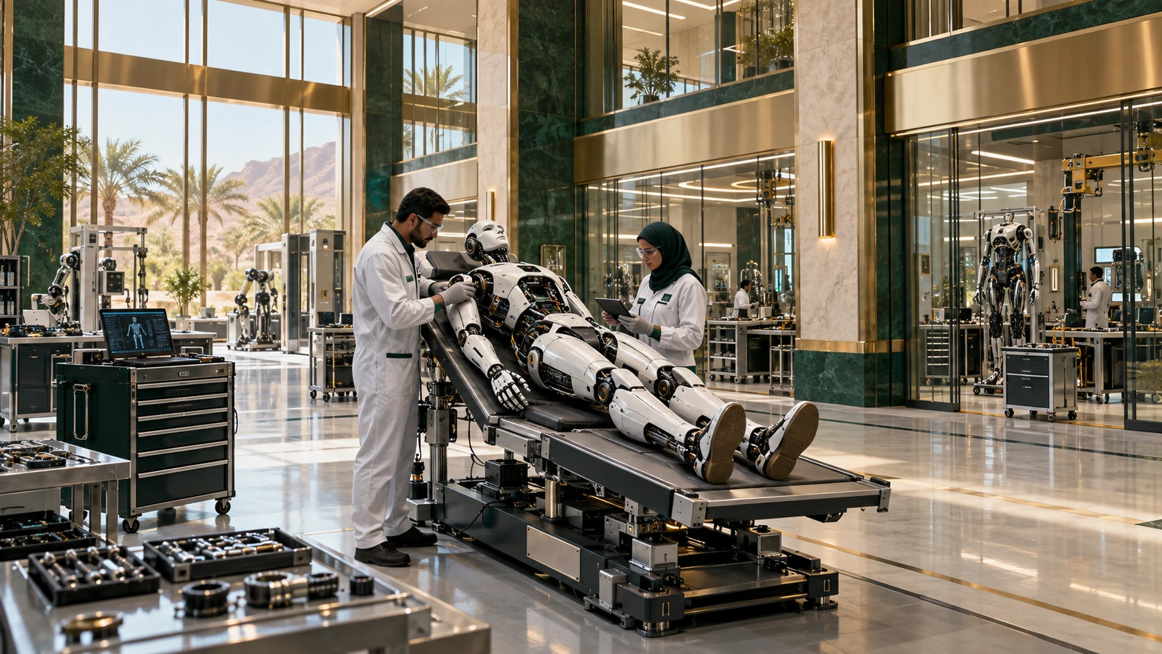
Assemble structures and joints, then integrate sensors, drives and computing, recording each stage and any configuration deviation.
Assembled unit and installation history.
Programming & calibration
Install the authorized software version and calibrate components against the product file before task testing.
Version and calibration record.
Quality & rework
Compile inspection results and identify limitations blocking simulation or delivery; keep rework units separate.
Documented progression or rework decision.
From intake to outcome.
An illustrative route linking the units and showing how work moves between them.
Configure product
Approve the use case and component list.
- 01
Configure product
Approve the use case and component list.
- 02
Assemble
Perform and document assembly stages.
- 03
Calibrate & test
Review motion, sensing and software.
- 04
Qualify
Hand a documented unit to simulation and identity teams.
Robotics Manufacturing Factory
The image proposes a relationship between work areas, circulation and service. Zones and materials can evolve; it does not establish engineering dimensions or approved final equipment.
How does the concept work in practice?
Initial reception prototype
A limited batch begins with one reception task. Test findings return to product engineering before larger-scale assembly.
An evaluable prototype and improvement record.
Clear ownership. Documented outputs.
System owner
Defines scope, authorized parties and case progression.
Specialist & integration team
Performs specialist work and connects outputs to related facilities.
Quality & review
Reviews records and exceptions before closure.
What does this area deliver?
01Assembled units with known configurations
02Component, version and calibration history
03Quality and qualification handover pack
What is reviewed before operation?
01Component and version traceability
02Resolution of consequential assembly defects
03Task testing before use-readiness claims
Proposed review areas, not a readiness certificate or operating approval.Connected to the wider city.
Continue into the detailed pages of related facilities and systems.